
The power Management board is one of the key components that the Maritime Digitalisation Centre (MDigiC’s) IoT Suite of Products Team has developed to support different edge processing devices and sensors while minimising power consumption based on mission planning. This custom-made board uses the Smart-Float’s battery 12V input and provides different voltages through DC-DC converters to our computing or communication modules. There is an option to charge the battery from a solar panel using an add-on board. This allows the charging circuit to be either upgraded in the future or use another type of battery that requires a different charging process.
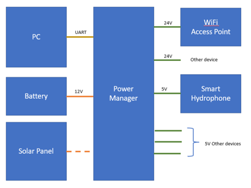
Figure 1: Block Diagram of Power Management Board
Each output can be controlled to switch on or off. This could be performed by direct commands or by pre-programmed time intervals or by any other suitable criteria. All output currents are measured so that the battery discharge can be estimated, so that appropriate measures could be taken to increase the mission duration. In addition, there are 4 motor current measurement inputs, where the propellers’ current (which is high) is also measured for the same purpose. The current measurements of the propellers can be used to detect faulty or problematic conditions in the future.
There is a wide range of output connectors for the DC outputs to facilitate connection of different computing devices or sensors. For example, the board supports terminal blocks, USB-mini and USB-C connectors.
For our experiments we needed more boards as these can be also used for powering ground-based trials. After the verification of the first prototype last year, we completed the assembly of most of our boards. We completed these boards by a clever just in time (JIT) design, based on currently available components and a fast design cycle of a few weeks.
The boards also provide UART, SPI and I2C busses to connect to a host or control auxiliary devices like GPS. It also provides a real-time clock as a reference for time activation of outputs.

Figure 2: Assembly of Power Management Boards
Our graphic control tool can test the basic functionality and ensure a full functional test before delivering the boards to the Intelligent Agents Team.

Figure 3: Testing the Power Management Board
Testing of the produced boards included firmware downloads, output testing, checking the current measurements and ensuring that the board complies to all requirements.
This board is used in the new generation of Smart-Float platforms that are developed for sensor testing and other activities.
For more information on this topic, you can contact MDigi.C@cmmi.blue